Topics List
Mar. 5, 2023 Updated
[UPDATED]Live Coverage: Launch of the First H3 Launch Vehicle (H3 TF1:Test Flight No.1) with Advanced Land Observing Satellite-3 “DAICHI-3” (ALOS-3) onboard
|
JAXA will provide the live coverage of the launch of the first H3 Launch Vehicle (H3 TF1:Test Flight No.1) with Advanced Land Observing Satellite-3 “DAICHI-3” (ALOS-3) onboard based on the new launch date. Broadcast Start: around 9:40 a.m. (JST) / 0:40 a.m. (UTC) on March 7, 2023 The broadcast date is subject to change due to the launch date. 
|
Feb. 14, 2023 Updated
[UPDATED]Live Coverage: Launch of the First H3 Launch Vehicle (H3/TF1:Test Flight No.1) with Advanced Land Observing Satellite-3 “DAICHI-3” (ALOS-3) onboard
|
The live coverage of the launch of the first H3 Launch Vehicle(H3/TF1:Test Flight No.1) with Advanced Land Observing Satellite-3 “DAICHI-3” (ALOS-3) onboard until the separation of “Daichi-3.” Broadcast Start:around 9:45 a.m. (JST) / 0:45 a.m. (UTC) on Feb 17 The broadcast date is subject to change due to the launch date. 
|
Feb. 10, 2023 Updated
Live Coverage: Launch of the First H3 Launch Vehicle (H3/TF1:Test Flight No.1) with Advanced Land Observing Satellite-3 “DAICHI-3” (ALOS-3) onboard
|
Broadcast:around 10:00(UTC-9) on Feb 15 The broadcast date is subject to change due to the launch date. |
Mar. 22, 2021 Updated
Completing the Wet Dress Rehearsal (F-0) of the H3 Launch Vehicle
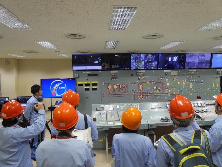
The alarm echoed once more through the control room, this time apparently signaling that the control system refueling the rocket had stopped due to a holdup in the liquid oxygen precooling. When fueling a rocket, liquid oxygen must be injected gradually to cool the feed lines little by little. Another halt in fueling…how many times did that make? The engineers rushed to check the data, quickly summarized the key points on the whiteboard and issued instructions on revamping the fueling approach. The plan called for the rocket to have been fully fueled by this time but not a single drop was onboard yet. I had anticipated it might be difficult to add cryogenic fuel to the rocket for the first time, but I had not expected it to be such a struggle. Doubts about whether the testing would go ahead left me frustrated. Retesting would have a huge impact on the project’s development schedule and cost. We eventually managed to complete the fueling after modifying the procedures several times, and this allowed us to move on to checking various rocket functions. Next was the 240-second automatic countdown sequence to the main event, the launch. Pressurizing the fuel tank for launch, switching from an outside power supply to the internal battery, and beginning to spray down equipment with water to protect it from the smoke produced at launch must be automatically performed in the preset order and designated times as part of the critical final preparations for the rocket and ground equipment. Combining a first-time rocket with first-time equipment only adds to the difficulty of this process. “240, 239, 238…” The countdown reverberated through the control room, and everyone fell silent as the tension in the room rose. "10, 9, 8, 7, emergency stop." This emergency stop seven seconds before main engine ignition was part of normal procedure. Miraculously, we were able to complete the first sequence in a single go, giving us a perfect score to that point. 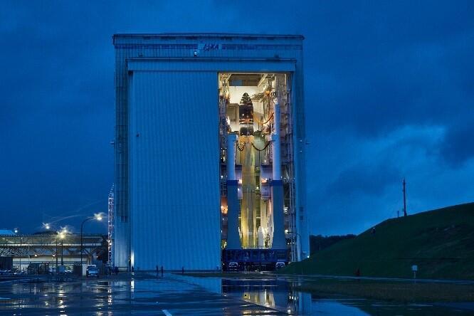
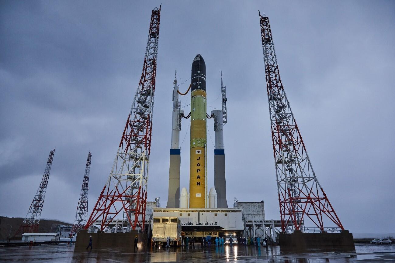
Launch Vehicle shortly before leaving the Vehicle Assembly Building (VAB) 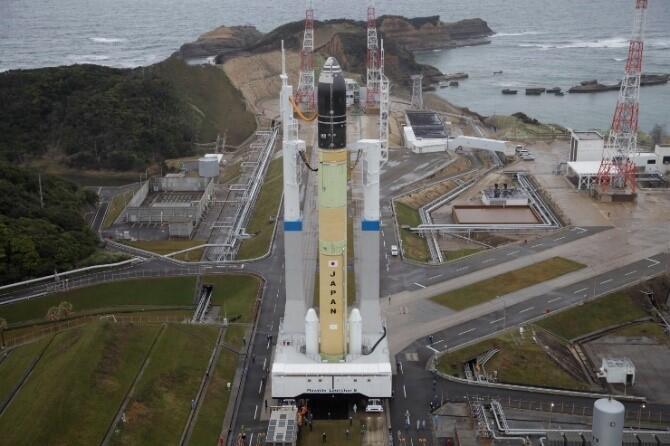
Launch Vehicle being returned post-test Once the tests had been completed, the Launch Vehicle was returned to the Vehicle Assembly Building (VAB) after its 36-hour outing. The rocket put through these tests appeared more reliable than usual, and no readily visible damage was sustained during the test. I feel certain we engineers also experienced some growth in the course of the testing. S.M., JAXA Rocket Team Leader |
Feb. 26, 2021 Updated
A Look Back at VOS (Vehicle On Stand) Operations
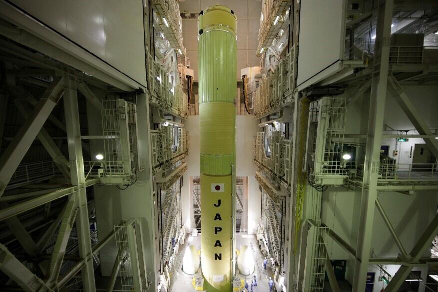
The first prototype H3 Launch Vehicle was finally placed on a mobile launcher (ML5: Movable Launcher 5) on February 6, 2021, the 11th 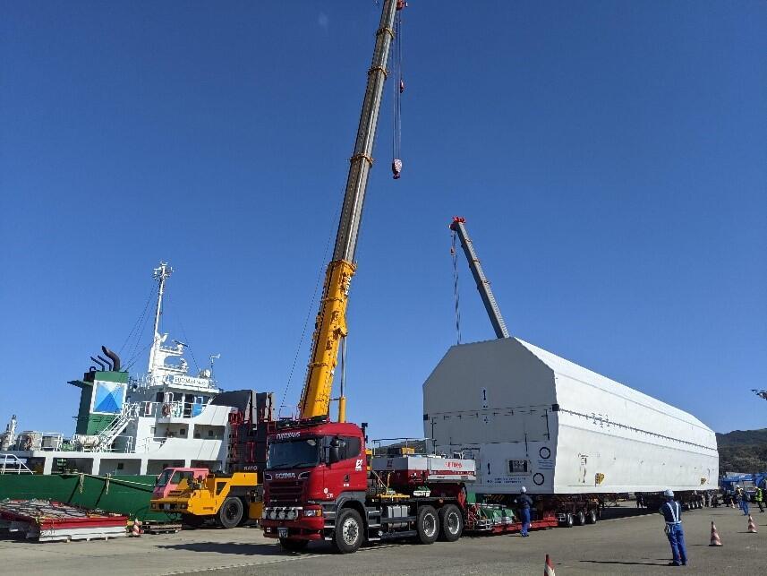
First stage of the launch vehicle arriving at Tanegashima When I caught sight of the huge container that had arrived at Tanegashima’s port, a mixture of excitement and anxiety hit me as I realized that launch operations were about to get underway at last. New challenges are part and parcel of VOS operations, and we inevitably find ourselves wondering if the equipment will work as designed. The standstills that occurred during transport on the island and the close call we had with the container just barely fitting through the VAB entrance only heightened my anxiety. Fretting gets you nowhere, though, and the only option is to deal with issues on the spot when they crop up. The stolid expressions on the faces of experienced senior colleagues and ground engineers seemed to reflect this mindset. Believing that the VOS operations would only be a success if everyone concentrated on what they could do at a given moment and thought for themselves while teaming up flexibly with the other personnel involved, I threw myself into my work with firm determination. 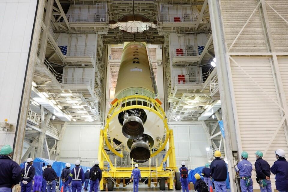
VOS operations for first stage The VOS operations for the H3 Launch Vehicle proved full of new challenges as we dealt with both a new rocket and new equipment/facilities needed for assembling the launch vehicle. The rocket was even larger that the H-IIB Launch Vechicle, the biggest heretofore, but the VAB where the VOS operations were to be carried out had not been resized. This meant handling larger objects in a more confined space, inevitably creating circumstances that heightened the risk of interference. 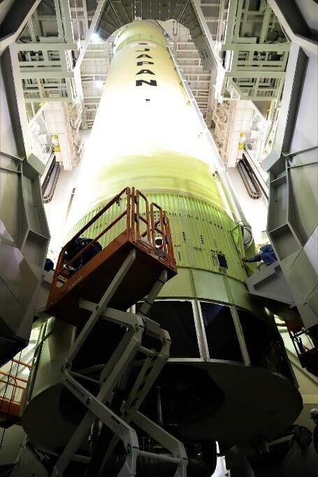
First stage placed on mobile launcher 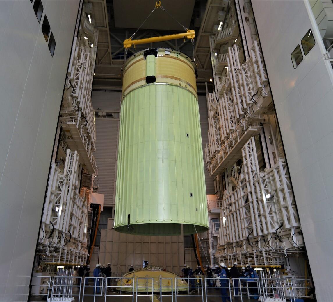
VOS operations for second stage Despite careful preliminary checks of the demanding work conditions we had been prepared for since the design stage, we found operations going off-track on several occasions. Time pressure is an integral part of H3 Launch Vechicle development, and we had to avoid causing any scheduling delays as we carried out the VOS operations. No matter how tight the schedule, though, it must be remembered that a single mistake in rocket development can literally prove fatal. Whenever I was unable to perform pre-assigned tasks, I made certain to follow the basic protocol of promptly halting my work and checking with everyone else involved to set up a new work plan, and then proceeded with my work carefully, putting safety first even while racing against time. 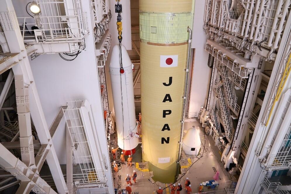
VOS operations for solid rocket booster (SRB-3) Encountering so many firsts during these on-site operations helped me make quite a few discoveries, even when things did not go smoothly. The site was a very busy one, and I was impressed at how spontaneously and pro-actively the workers and engineers took time out to devise improvements together. I sensed a commitment throughout our workplace to making the H3 Launch Vehicle better and its successor better still, and I was pleased to be doing my part as one of the next generation and extremely grateful for the experience gained from joining the discussions as a somewhat giddy participant. Clearing one hurdle after another, we managed to successfully complete the VOS operations for the first H3 Launch Vehicle prototype. The workers’ careful handling of the vehicle was very impressive, and any sense of fatigue I felt disappeared as soon as I saw the rocket assembled so exquisitely from top to bottom. Nevertheless, the tasks of installing equipment and devices and checking their functions still lie ahead, so launch operations have only just begun. I am firmly resolved to continue doing my best. CHOFUKU Shintaro, JAXA Structural Engineer |
Jan. 28, 2021 Updated
First test flight rocket shipped from plant
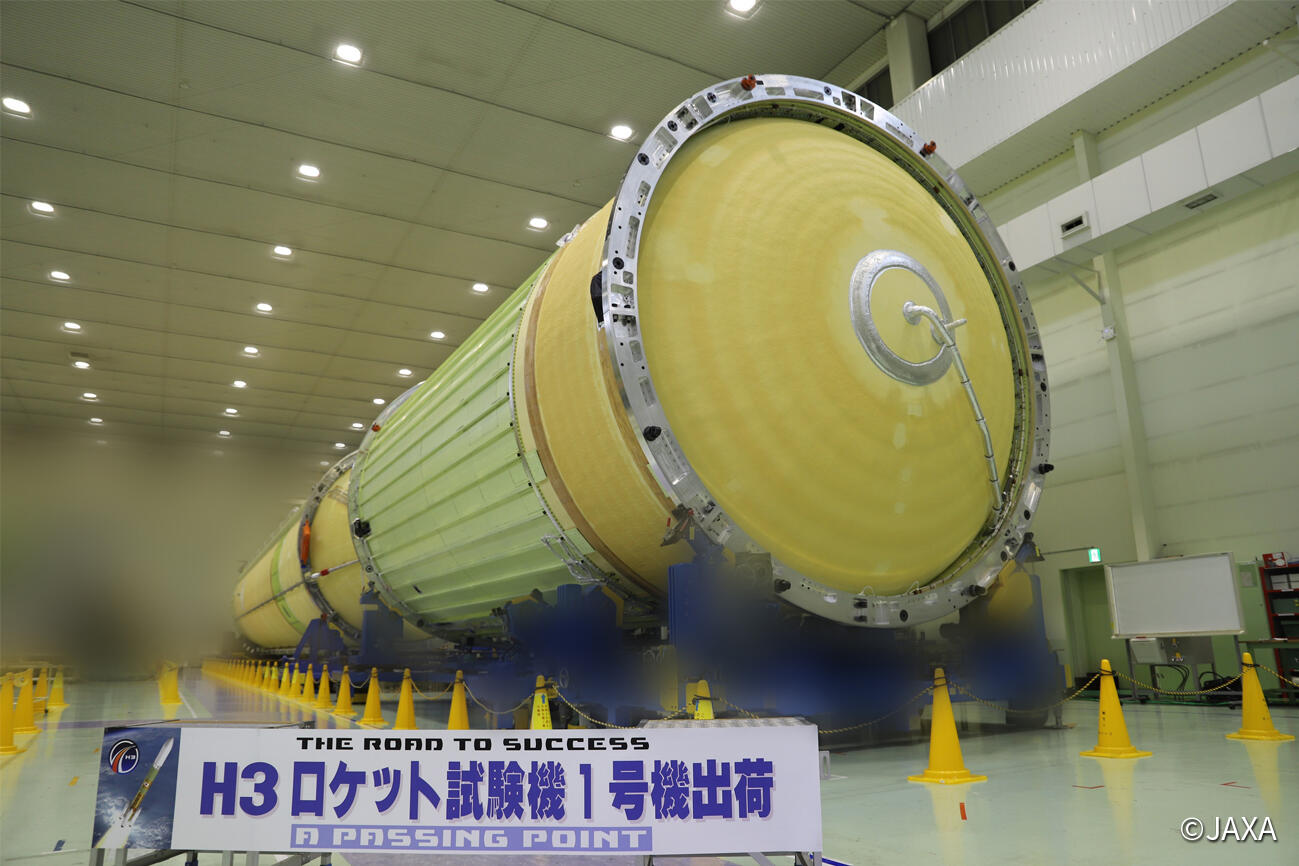
Manufacture and testing of the first and second stages of Test Flight No. 1 (TF1) of the H3 Launch Vehicle were completed on January 26, 2021 at the Tobishima Plant of Mitsubishi Heavy Industries, Ltd., from which it was shipped to its launch site, the JAXA Tanegashima Space Center. Much of the equipment comprising the rocket had been developed and then assembled at the Tobishima Plant, where functional tests got underway in early June 2020. Encountering numerous problems of varying scales and resolving them one by one until the equipment was in perfect shape required almost seven months. Remembering back even further, testing on the electrical system that was my responsibility began at this Tobishima Plant, and I first witnessed one of these tests in February 2018. We encountered a significant number of problems thereafter, and three years passed in the course of resolving each and every one of these. When we had assembled the electrical equipment still being developed to ready it for technical testing and were set to begin system tests three years ago, we started off by lining up more than a dozen devices about the size of an orange crate in a brand-new but bleak-looking area still under construction as part of expansions being made to the Tobishima Plant for H3 manufacture and then testing them (in rather low-key and rudimentary tests) to check on the data interfaces for network communications between devices. I am deeply impressed that, over the next three years, we managed to put together such an attractive rocket of such astonishing height. The world has entered a time of great change due to the coronavirus pandemic. We at JAXA as well as the engineers at Mitsubishi Heavy Industries, which is coordinating the rocket’s overall design, and at manufacturers in charge of designing and manufacturing equipment have been able to employ alternate means such as sending and receiving design materials over networks and utilizing web conferencing to pursue design and review efforts on par with those using conventional means as we have continued development, but there is no substitute in rocket development for hands-on work onsite. Even as they did before the coronavirus pandemic, numerous manufacturing professionals and engineers have struggled days, nights and holidays for seven months at the Tobishima Plant. I am always impressed by the team members at the manufacturing site who have maintained a record of consistent performance even as their day-to-day world changes, and I strongly felt that this workplace was imbued with a spirit that must never be lost no matter how much the world transforms. Spending so many days witnessing the work done at the Tobishima Plant gave me a valuable opportunity to gain new knowledge, experience and the companionship of many kindred spirits. It took the support of countless people to complete the first and second stages and, though these have been shipped from the plant to the launch site, the road ahead for verifying the rocket’s viability as an integrated system is a long and steep one. Even so, I feel almost no anxiety or pessimism and, gazing at this launch vehicle, I am very excited and thoroughly convinced that we can overcome whatever is thrown in our way. I look forward to reaching our goal of a successful launch with renewed determination. Y.K., JAXA Electrical System Engineer 
The first and second stages of the H3 Launch Vehicle being put into containers for shipment (photographed on January 24, 2021) |
Oct. 29, 2020 Updated
Revising H3 Launch Vehicle Development Plan
|
In May 2020, a series of qualification firing tests was performed on the LE-9 first-stage engine for H3 Launch Vehicle at the Tanegashima Space Center. Before finalizing the engine design, rigorous firing tests needed to be performed over 10 times on a test engine, which was designed and produced in the same way as the one to be used in the actual launch. The eighth firing test was completed on May 26, with the total test time reaching 1098.5 seconds. As we were about to proceed to the next test amid the intense atmosphere of the final stage preceding the first test flight, I received a call on the morning of May 27 from the development leader who had been present at the post-test internal inspection of the engine. “We identified a change in the interior wall of the combustion chamber. It requires careful observation,” he said. Such an unexpected phenomenon occurs quite often in the course of development, so I always try to keep calm and gain an accurate understanding of the situation, but my voice must have sounded tighter than usual upon hearing the news. Following this incident, we made concerted efforts over three months to look at measures to identify and resolve the cause of the issue, along with the fatigue fracture that surfaced on the turbine for the liquid hydrogen turbopump. Desperate to find a way to launch H3 by the end of fiscal 2020, we explored a wide range of possibilities. As part of our efforts, we embarked on a new test in which we affixed a sensor to the turbine rotating 700 times a second to acquire data. As the cause of the phenomenon was clarified, we were able to come up with a concrete solution, but we considered that sufficient time should be spent on implementing it. In project management, the way forward needs to be adjusted on a daily basis by constantly considering the balance between time, costs, and the quality of the product. However, if a good balance cannot be achieved (which should not be the case), we must change the conditions. This is when we are pressed to make the ultimate decision as to what we should value the most. In due course, we concluded on September 11 that, if we were to properly address the issues we faced, we would not be able to launch the first test flight by the end of fiscal 2020. We therefore announced the postponement of our planned launch. We are deeply apologetic to all those involved in the satellite mission, who have pinned their hope on the test engine, all those who have been involved in the project, directly or otherwise, and all others who have been watching over us with supportive warmth. We ourselves are also immensely disappointed. Precision, honesty, and elimination of ambiguity are essential in handling technology. We have no choice but to squarely face technical barriers that confront us. It is our mission to address the problems with conviction and come up with impeccable H3 Launch Vehicle. I would also like to mention that many people within and outside JAXA have kindly extended their support to us in postponing our plan this time. JAXA upholds the philosophy that all employees must make maximum efforts in their respective capacities to achieve a successful project. The H3 project has opened our eyes to a notion that goes far beyond the philosophy—the fact that a project cannot be achieved “alone.” By “alone,” I do not mean “a single person,” but “those involved in the project.” I wish to take this opportunity to express my deepest gratitude to all of you for providing support to us from nearby and afar. Members of the H3 project team are currently trying to get back on our feet with all our partner entities, making elaborate plans for the days to come. If I were to use the metaphor of mountain climbing, I could say that we had conquered nine-tenth of the altitude, but have had to descend by one-tenth, which has given us some extra time. We would like to climb up again step by step, aiming for the apex with certainty. Please watch over us with warm and demanding eyes. We appreciate your continued support.
October 29, 2020
|
Jul. 27, 2020 Updated
Functional test of the first H3 Launch Vehicle
|
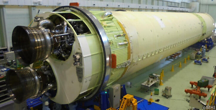
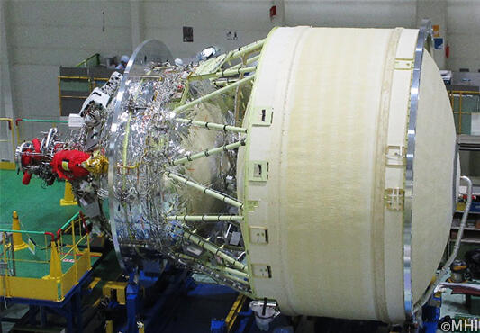
The first stage body and the second stage body of the first H3 Launch Vehicle are now undergoing a functional test at the Tobishima Plant of Mitsubishi Heavy Industries, Ltd., in Aichi Prefecture. (Left photograph) The first stage body of the first H3 Launch Vehicle is lying impressively on the ground. It has a diameter of 5.2 meters and a length of 37 meters, which is equivalent to the size of two cars of the Yamanote Line. The long, cylindrical, cream-colored portion is the liquid hydrogen and liquid oxygen tanks that carry fuel. The lower part seen in the foreground is two LE-9 engines mounted on the first stage of the rocket. (Right photograph) The second stage body of the first H3 Launch Vehicle. The cream-colored portion is the liquid hydrogen tank, which was 4 meters in diameter for the H-IIA rocket, but is 5.2 meters in diameter for the H3 rocket. The liquid oxygen tank wrapped in silver insulation is coupled to the LE-5B-3 engine (nozzle not installed). The two-stage body is equipped with structural components that support the fuel tank, pipes that lead fuel to the engine, and electrical equipment to control the body. It gave me a sense of accomplishment to see for the first time the components, which we have worked hard to complete, assembled as an actual launch vehicle. At the same time, it made us further determined to make the scheduled launch successful. The functional test currently underway is the process of verifying numerous rocket functions one by one. The following tests are conducted: a test to check whether the function of distributing power to each device is correct; a test to check whether signals from various sensors are outputted correctly; a test to check whether there are no leaks in the fuel pipes and valves are working properly, etc. After these tests, the first stage body and the second stage body are electrically connected and the same sequence at the time of actual launch is applied to operate each device and valve to confirm that signals are properly outputted. This is the first functional test for H3 Launch Vehicle Once we start functional tests, we realize that there are things that don’t go smoothly as we expected. We move forward by solving problems one by one. The rocket bodies show their imposing appearance, but their inside as unsteady as legs of a newborn fawn. The power distribution test is conducted at first. The switches of hundreds of items are turned on one at a time to check the voltage output of each line. However, various problems can occur including a simple problem in which a switch cannot be found, or another problem in which communication fails because of a slight time lag of signals among equipment. By the time the rocket is shipped out of the plant, we need to make a full-fledged rocket. There have been several cases of failed rocket launches in the past problems of which could have been found during functional tests at this plant. We want to proceed with the functional tests carefully and without haste to check items so as not to overlook anything. If we successfully complete the functional tests at the plant, we will carry the body of the first H3 Launch Vehicle to the Tanegashima Space Center where we assemble the rocket and conduct an integrated system test to confirm the interface between the rocket and the ground facilities. The top of the mountain is finally in sight as we prepare to launch the first H3 Launch Vehicle. We will continue to brace ourselves for the remaining works. |
May 25, 2020 Updated
The LE-9 engine firing test.
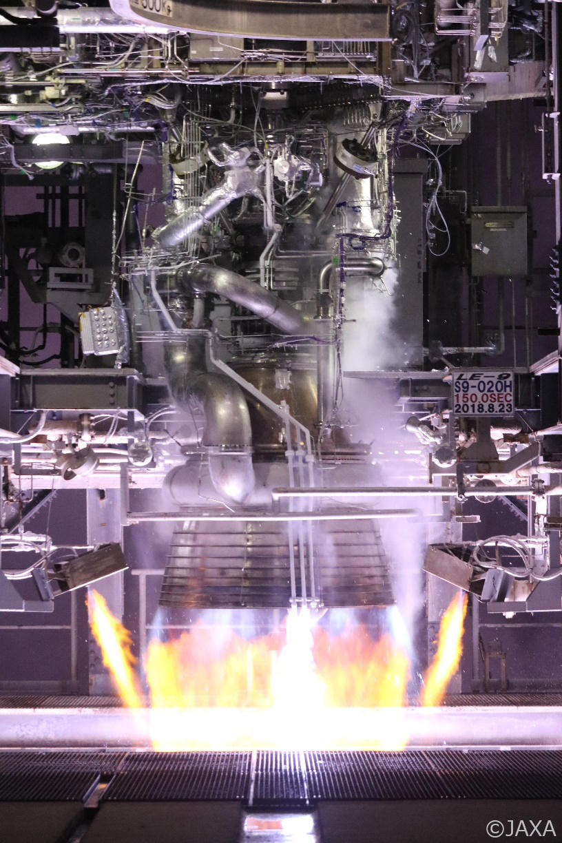
It always seems impossible until it’s done. Nelson Mandela The development of rocket is always extremely difficult. Rockets are made up of a variety of small and large components, and typically have about one million parts. Rigorous verification tests are conducted on nearly all of them. Sometimes tests go well and sometimes they don't, but more often than not, tests don’t go well in rocket development. The most difficult part of rocket development tests is the engine firing test. If a rocket is compared to a human being, its engine is the heart that generates energy. An engine draws in about five drums of cryogenic liquid oxygen and liquid hydrogen per second at minus 200 degrees Celsius, burns them into hot gas at about 3,000 degrees Celsius, and then jet it out at supersonic speeds to generate the propulsion necessary for a rocket to reach space. As a result, the inside of the engine is subjected to extremely low and high temperatures, ultra-high pressures and severe vibrations. For this reason, engines are prone to failure, and many of the world's rocket failures are attributed to engines or related parts. In addition, engine development is a continuous struggle with failures, and the engine firing test is said to be the most difficult part of rocket development. The firing test of the LE-9 engine is being conducted at the JAXA Tanegashima Space Center. The firing test stand used for the development of the LE-7A engine mounted on the H-IIA/B rockets was modified and has been used for the LE-9 engine test. The firing test stand is located only a few hundred meters away from the launch pad, making it one of few places in the world where high-risk engine firing test and rocket launch are in close proximity to each other. As mentioned above, an engine burns about five drums of propellant per second. Since the propellants for LE-9 are oxygen and hydrogen, the combustion creates water vapor. The large amount of water vapor produced in a firing test is lifted into the air and sometimes creates a beautiful rainbow. A rainbow that appears in the background of Tanegashima Island’s beautiful sea is a spectacular sight that only those who are involved in the project know about. 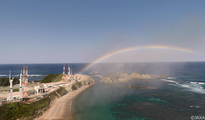
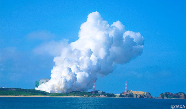
The control room is filled with an indescribable sense of tense at the moment when an engine firing test starts. Sometimes an engine is designed and manufactured based on various simulations and elemental experiments conducted over several years. Firing tests will determine whether such efforts have been correct. There is a phrase in the world of bullfighting: "The moment of truth". It's the moment when a matador delivers the final blow to a bull. Analogously, it can be said that an engine firing test is the moment of truth. This is the moment that determines the success or failure of efforts made by so many people involved over the years. We can never get used to a firing test, no matter how many times we go through it. It always feels like losing a few years off our life. 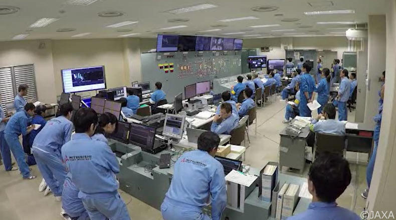
Unfortunately, the results of firing test are often different from the design intent. In the worst case scenario, there can be a serious failure that destroys part of engine, which requires us to stop the engine in an emergency. Whenever a breakdown occurs, people involved agonize over the failure and think hard about countermeasures all night long. The harder engineers have worked and the more confident they have become in their design, the more impossible they feel that they can solve the problem when a failure occurs. But we don't give up and solve problems one by one. In this way, we have conducted the LE-9 firing tests for 38 times so far. There are 6 more times to complete the development of the engine for the first H3 Launch Vehicle, and 24 more times to complete the development of the engine for the second H3 Launch Vehicle. The goal is still a long way off, and we can't imagine the successful completion of the development yet. But we believe we will make it through, and today we have another moment of truth. It always seems impossible until it’s done. H.K. in charge of JAXA LE-9 |
Apr. 17, 2020 Updated
“Test as You Fly, Fly as You Test”~Toward a successful launch of the first H3 Launch Vehicle
The LE-9 engine firing test facility. “Now, we'll start the firing test sequence. 3, 2, 1, 0...The sequence has started.” The test engineer's voice echoed in a tense atmosphere. He stares at the monitor, his hand on the emergency stop button. The calmness of the test engineer, who has gone over and over the procedure many times and knows it inside out, calms members' nerves. “Test as You Fly, Fly as You Test.” The H3 project was launched in April 2014. Nearly 2,200 days have passed since then. If it is a mountain climbing, we (staff of many companies and JAXA) are now past the eighth station and just beginning to see the summit in the distance. H3 is a system (a collection of rockets and equipment) aimed at supporting a society, which continues to undergo drastic changes, supporting people's secure and prosperous lives from space, and supporting the quest for space and the Earth. The system is also aimed at being used as a space transportation service by people not only in Japan but also around the world. Since H3 has such a clear mission, we thought at the beginning, "What role will the whole project perform to fulfill its mission, and how will we use it?” For this reason, we made a manual in advance. We then divided the roles of large system to those of several smaller elements that make up the whole (if it is a human body, its roles are divided into the elements of head, body, hands and legs). At this point, we carefully deliberated over "How should we divide the roles to each element? What should be the relationship among them (interface)? (Humans can think with their minds and grasp things with their hands, but robots can think with their hands, too. It's important to think from the ground up about where and what role we want the entire system to play). In this way, we first allowed each company and engineer to share works, and then we designed and made prototypes, and if necessary, repeated basic tests. We explained in a nutshell, but each element is a mixture of new technologies that we have never experienced before and well-experienced technologies with varying degrees of hurdles to overcome and time to get over them. Sometimes we stop because things don't go as we expected or we even have to go back. There were times when we were lost in a maze because we were unable to find ways to solve a problem. Also, communication between people is very important for interface between elements, but there were times when we were at a loss because we understood each other in a different way. And now. Elements that have crossed high hurdles are being completed one by one and integrated into a system. Controllers are set in the engine body of the all-electrified LE-9 first stage engine, the LE-9 is connected with the fuel tank, the solid rocket booster is set in the first-stage rocket, the precision accelerometer is set in the on-board computer, the on-board transmitter is set for communication with the new tracking station on the ground, the movable launcher is set on the dolly ... Time left before the scheduled launch is about one year. As we continue integrating systems, we are taking on a challenge by conducting large scale tests and climbing a much steeper hill to the top of the mountain. The first H3 Launch Vehicle, which have been unseen, is slowly making its appearance at the manufacturing plant. Tanegashima Space Center H3 Launch Control Complex, commonly known as LCC. “We will now start the final countdown sequence for the launch of the first H3 Launch Vehicle..... The sequence started.” We would like to report the progress of the H3 project in more detail and in a more realistic manner until the first H3 lifts off. JAXA H3 Project Team |
Dec. 27, 2019 Updated
Fairing Separation and Release Test
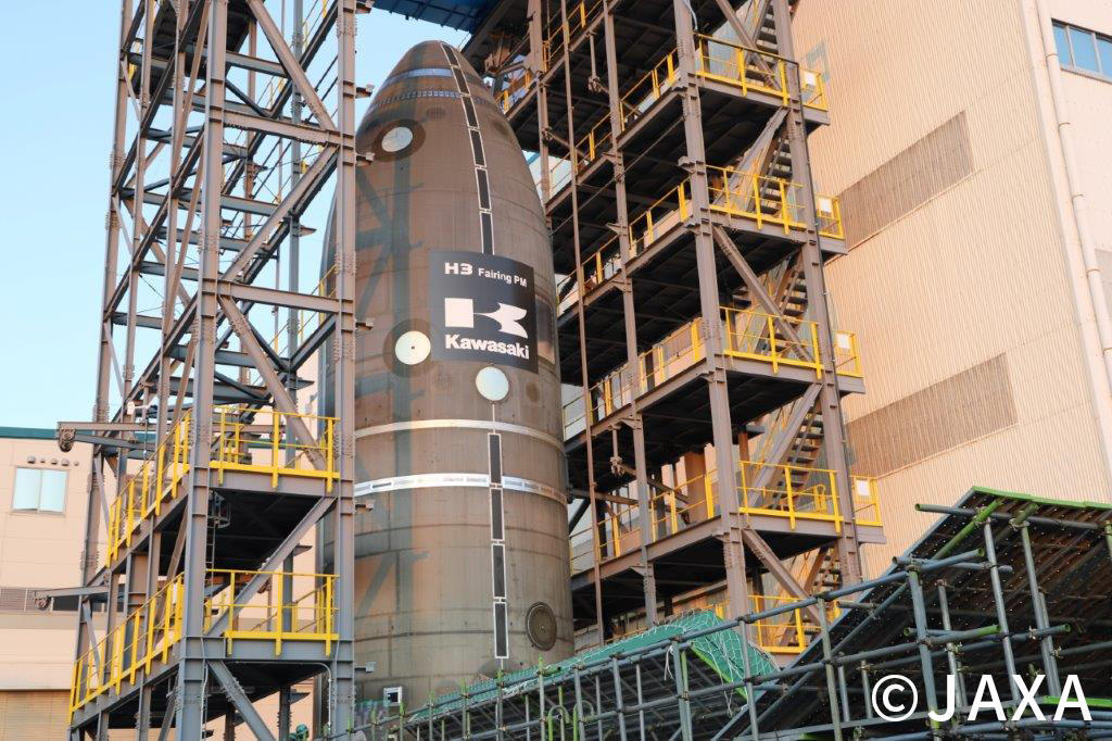
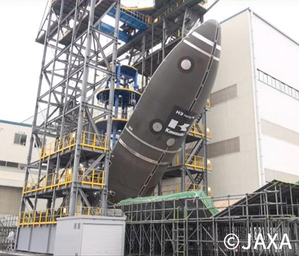
On December 17, 2019, with the end of the year just around the corner, a fairing separation and release test was conducted at Kawasaki Heavy Industries' Harima Works in Hyogo Prefecture. The fairing is located at the tip of rocket and serves to protect payloads from the forces generated by the atmosphere and the heat generated by aerodynamic heating during a rocket's flight through the atmosphere. The separation and release test is a test to verify that a fairing splits apart and is released from the rocket as designed by activating the separation mechanism under the actual flight condition. It is also the last test of the H3 fairing development that took about four years. Technologies that have been successfully used for the H-IIA/B rockets and the Epsilon launch vehicle are utilized for the H3 fairing, and we are also actively introducing new technologies. A typical example of the proven design is the separation mechanism. The separation mechanism used for the the H-IIA/B rockets and the Epsilon launch vehicle has not undergone any major design changes, maintaining its reliability, which is the most important to the fairing. On the other hand, a typical example of newly adopted technology is the switch from aluminum to carbon fiber-reinforced plastic (CFRP) used for the surface material of the main structure (honeycomb panel). In conjunction with the change in materials, manufacturing methods were also updated by introducing a new device that can automatically stack CFRP sheets when manufacturing the honeycomb panel. Each honeycomb panel has been enlarged in size, drastically reducing the number of panels that need to be joined together in the final assembly process, which contributes to reducing the overall manufacturing cost of the product. The application of CFRP has also made it easier than ever to create complex curved configurations, allowing the entire fairing to be formed on a smooth, streamlined and curved surface. By changing the shape of the fairing, aerodynamic drag is reduced and launch capacity is enhanced, while air flow around the fairing is also stabilized, contributing to reducing vibration environment. In addition, the heat-resistant insulating material that protects the fairing from heat was switched to an adhesive type that has a proven track record from the launch of Epsilon Launch Vehicle, eliminating the need for the specialized coating booth that was required for the conventional spray-on type, and allowing us to provide insulation using simple manufacturing equipment. The fairing is the subsystem closest to the “customer” of rocket, which is payloads, with the role of gently wrapping and protecting the payloads until they are delivered to space. The fairing a very important subsystem because customer service is very important for H3 Launch Vehicle. The new technologies mentioned above give us the flexibility to meet customer’s requests (for example, where to install the doors to access payloads and when to decide their positions). |
Oct. 10, 2019 Updated
SRB-3 qualification motor ground firing test was conducted (Part 1).
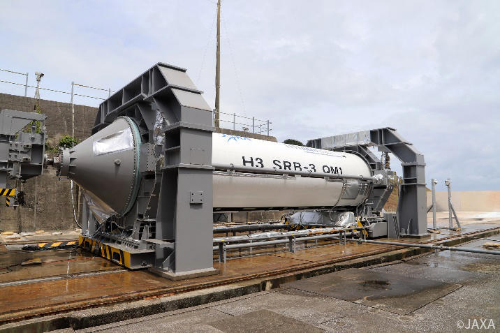
On August 28, 2019, a ground firing test (Part 1) of SRB-3 qualification motor of solid rocket booster was conducted at the Tanegashima Space Center. The purpose of this test is to determine the design, manufacturing and inspection process of the motor to be used for an actual flight. The firing lasted for approximately 100 seconds after ignition as planned and the test ended successfully. From now on, the acquired data and the motor after combustion will be evaluated in detail. This was the second firing test for SRB-3. The test started with a hardship as a typhoon hit Tanegashima Island on the day the motor was scheduled to be moved to the test site. The original plan was to move the motor to the test site in the early morning of August 16, but as a typhoon hit Tanegashima Island on August 15 and was expected to have an impact on the morning of August 16, the movement was delayed by half a day. As a result, it was decided to move the motor to the test site in the evening of August 16. Even if we are dealing with a typhoon, we can't waste even a day of our development schedule. We managed to make up for the delay caused by the typhoon a few days later by coordinating smoothly with all parties involved, not to mention the efforts of those working on site. After moving the motor to the test site, we proceeded with the final preparatory work by assembling the motor with the test equipment, as well as with the preparation and inspection of the equipment. On the day of the test, all the people involved started gathering at the test center one after another for the preparation of the test. The atmosphere of "it's finally happening" was building up. We then ignited the motor at 11:00 a.m. on August 28 as scheduled. The firing lasted about 100 seconds as planned and the test was completed. Until the data is evaluated, it is impossible to judge whether the motor worked as designed, so unlike a rocket launch, there were no cheers after the firing ended. Workers proceeded with the after-test process while they were relieved that the test was successfully completed. The test facility for solid rocket motor firing test at the Tanegashima Space Center has a long history. It was built about 50 years ago, the same time the center was opened. The foundations and main equipment, which are the key to measurements, were made in those days and are still in use today. Although even JAXA personnel rarely visit the test site, it is one of the important places that have witnessed the development history of solid rocket motors used in Japan's large rockets. This is where the history of SRB-3 is being added right now. While workers bask in a transient sense of accomplishment after the success of the test, they return to their busy days, evaluating the test results, planning the next test, inspecting the test equipment, and preparing the test motors so that they will become fully ready for the next test. Ground Firing Test for New Solid Rocket Booster |
Aug. 6, 2019 Updated
~ A force behind the scenes~Rocket transporter
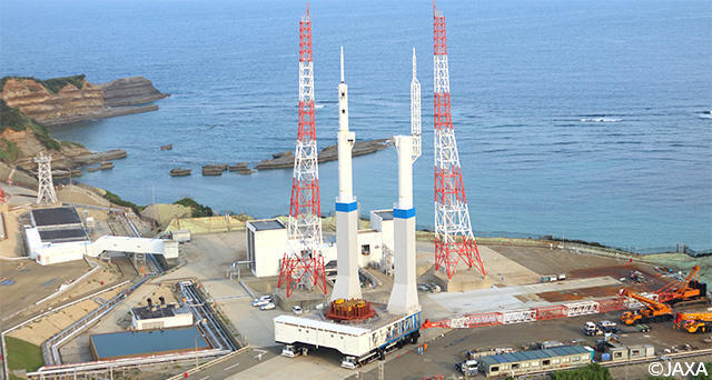
The Movable Launcher (commonly known by ML) is the platform used to assemble a rocket at the final stage at the Tanegashima Space Center. On the day of launch, the ML carries the rocket from the Vehicle Assembly Building (VAB) to the launch pad, fuels the rocket and is used to conduct the final checkups until the last moment before the launch. It also plays the role of launch pad when launching a rocket. JAXA has developed a new ML for H3 Launch Vehicle, which was manufactured, tested, and inspected at the factory in early November 2018. Then the new ML was transported to the Tanegashima Space Center by sea in seven separate shipments. It was assembled on the island. Since then, the ML has undergone various maintenance and inspections. From June 2019, test runs in combination with a ML transporter (commonly known as a "dolly") has been conducted at the large rocket launch site. 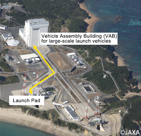
During the first test run, which started in mid-June and lasted several days, the two dollies lifted the new ML, entered the launch pad and traveled about 500 meters between the Vehicle Assembly Building and the launch pad. In the subsequent test in late June, a test was conducted by loading the same weight as the main body of H3 Launch Vehicle. Currently the electrical equipment inside the ML is inspected. From now on, we plan to conduct the functional and performance test of the ML in combination with other equipment and then move on to the integrated system test by combining with an airframe. We are going to explain the features of the newly developed ML and Dolly! 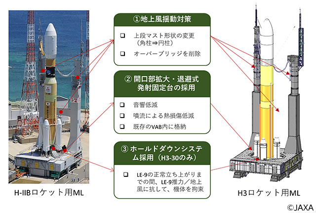
Here's the great part! ~The New Movable Launcher (ML)~
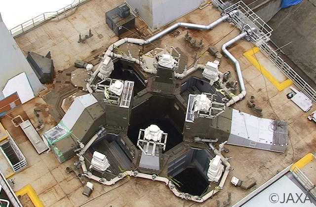
ML for H-IIB Launch Vehicle 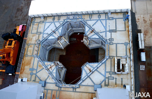
ML for H3 Launch Vehicle Reduces thermal damage during launch.By making the opening wider than the current ML for H-IIA/B, damage to the structure due to heat from the jet stream at the time of launch can be reduced. In addition, the pipes for propellant, high-pressure gas and water, and the platform to fix airframe on the upper deck were removed. This makes repairs after launch easier and reduces the interval between launches. Reduce the sound at the time of launchThe launch pad is equipped with a water injection system to reduce the sound generated during the launch. The current ML for H-IIA/B rocket has also a water injection system, but in the case of H3 Launch Vehicle, by enlarging the ML's opening to reduce the noise generated, the volume of water injection is reduced, aiming to simplify the water injection system. In addition, by moving components equipped with the ML to the ground eliminates the works needed to connect the water pipes after the ML arrives at the launch pad, which improves its operability. 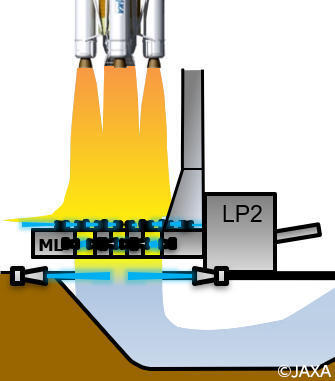
H-IIB Launch Vehicle 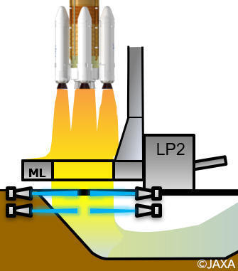
H3 Launch Vehicle The way to support a rocket is different!The ML for H-IIA/B ML supports the rocket body with four pedestals installed on the surface. On the other hand, the ML for H3 has four movable support structures attached to the side of the enlarged opening that upholds the rocket body. This makes it possible that H3 Launch Vehicle, which is 6.4 meters taller than the H-IIB rocket, can be assembled in the existing Vehicle Assembly Building. In addition, the support structures are retracted into the inside ML to prevent them from being damaged by the jet stream of rocket engine, which shortens the repair work after launch. 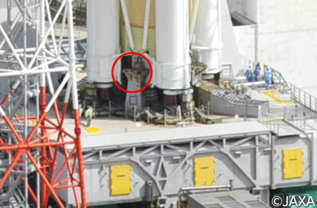
H-IIB Launch Vehicle 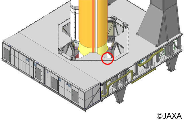
H3 Launch Vehicle In this way, various ingenuities make it possible to drastically reduce the time required to repair facilities after launch and the interval between launches from about two months to less than one month.
Here's the great part! ~The new DollyThe ML transporter, commonly known as a "dolly," plays the role of transporting an ML loaded with a rocket from the Vehicle Assembly Building to the launch pad. After a rocket is assembled and its maintenance is completed, dollies lift a rocket on a movable launcher and run and stop automatically by detecting the magnets buried in the ground One dolly has 56 wheels and two dollies lift a ML. A rocket is carefully carried at a speed of 2 km/h, which is slower than a person walks. Increased reliabilityIn the event of a breakdown, the newly developed dolly can recover and continue work within 30 minutes. Lower maintenance costsAnnual maintenance costs were reduced by more than half by using many general-purpose parts. This was realized also by introducing a self-check function and by inspecting some of the items, which were previously checked periodically, as necessary through monitoring integrity data. Increased operabilityBased on the operational experience with H-IIA/B rockets, parts for H3 Launch Vehicle are arranged for easy maintenance. Those parts can be used not only for H3 Launch Vehicle but also for the H-IIA/B rockets. 
H-IIA/B Launch Vehicle 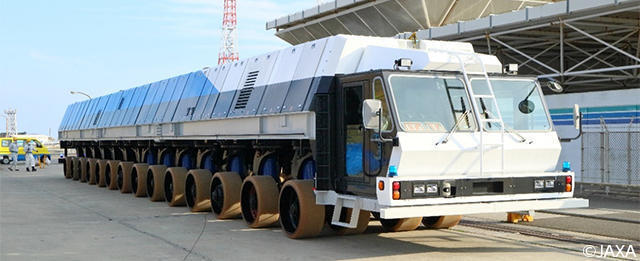
H3 Launch Vehicle In this way, preparations for the maiden flight of H3 Launch Vehicle scheduled for fiscal 2020 are steadily progressing on the ground facilities that are indispensable for the launch of rocket. New Movable Launcher for H3 |
Jun. 18, 2019 Updated
SRB-3 Full-Scale Separation Test
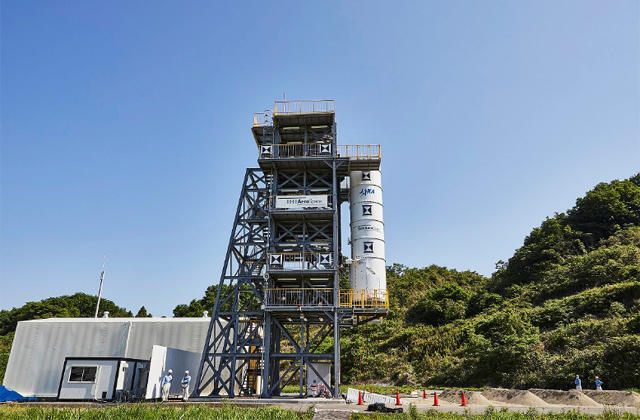
It's hot in May in Tomioka City, Gunma Prefecture, where lush green grass and trees give the appearance of early summer. It's so hot as if cicadas might start singing any minute now. A large white tower sits in the test site of IHI Aerospace (IA) Tomioka Plant located in the mountains. The white tower waiting quietly for a test to start is SRB-3, the solid rocket booster of H3 Launch Vehicle. The separation test of SRB-3, which is being developed mainly by IA, will be carried out at the IA Tomioka Plant. This separation test is to confirm that the SRB-3 and the H3 core airframe can be separated as designed. The method for connecting SRB-A with the core airframe of the current H-IIA/B is different from SRB-3. In H-IIA/B, thrust struts and arms extend from SRB-A to the core airframe, as if hugging onto the core airframe. But in the case of the SRB-3, it uses a method of hooking itself to the core airframe using a pin. A simple way to use pin to connect with the core airframe contributes to reducing costs and maintenance hours of the H3 rocket. On May 22, a so-called rehearsal was conducted to simulate the same movements as those to be checked in the test scheduled for the following day. The rehearsal itself was completed without a hitch, but in order to increase the probability of success of the test as much as possible, each test team meticulously listed what-if occurrences after the rehearsal and discussed them. Their foreheads were wet with sweat and their fatigue was evident from long hours of preparation, but their eyes were sparkling and their morale was high. The rehearsal ended with confidence that if weather conditions were right, the test could be conducted as scheduled and would be certainly a successful. A blazing sunset that foreshadowed tomorrow's clear skies was shining on the test site where workers had left, turning the white tower of SRB-3 red. On May 23, the day of the test, a meeting was held early in the morning. A tense atmosphere that was not felt during the rehearsal filled the test site. After reviewing the testing procedures, the process started at 10:20 a.m. Dozens of hours were spent for preparation and a few seconds for the test. An enormous amount of effort was exerted for the preparation of the test in a single moment. The test plan was drawn up, and various confirmation meetings were held to confirm that there was no problem in conducting the test. A path has been made by human feet at the test site where weeds are growing. We did the best. Leave the rest to God. 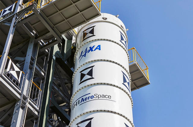
SRB-3 specimen waiting for the moment of separation. 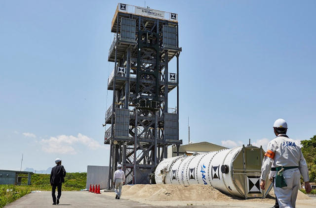
After separation. SRB-3 Full-Scale Separation Test |
Apr. 16, 2019 Updated
The First Stage Battleship Firing Test
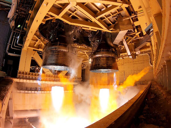
Going deep into a woodland path leading to Mount Tashiro in Odate City, Akita Prefecture, there is the Tashiro Test Facility of Mitsubishi Heavy Industries, Ltd., near the famous Shirakami Mountains, a World Heritage Site. A firing test, which is the climax of the development of the first stage propulsion system of H3 Launch Vehicle, is now being held. This firing test is called the "First Stage Battleship Firing Test." The First Stage Battleship Firing Test is a comprehensive firing test in which the propellant tank and the engine are combined to simulate the pressure and temperature of flight on the ground. The name "battleship tank" is so called because a sturdy thick tank made of stainless steel is used during the test instead of aluminum alloy tank on the actual rocket. The name in English is Battleship Firing Test, and the literal translation is a warship (because a sturdy tank like a warship is used) firing test. Those involved in the project call it BFT, the acronym of Battleship Firing Test. The LE-9 engine firing test, which is being held in Tanegashima, is the firing test of a “single engine,” but in the BFT, the same components of the real rocket are used except for tanks, and the LE-9 engine consists of two or three engines (called a "cluster") of the real rocket. The BFT in the form of two engines of H3 Launch Vehicle started in January 2019. The test is being conducted mainly by three companies: (1) Nagoya Aerospace Systems Works (commonly known by “Meiko”) of Mitsubishi Heavy Industries, Ltd., which is in charge of the entire test; (2) Nagoya Guidance and Propulsion Systems Works (commonly known by “Meiyu”), which is in charge of engine and turbopump development; and (3) IHI Corporation; as well as with cooperation of many relevant contractors and local companies. On the day of the test, work will begin in the middle of the night, starting with filling the propellant tanks with liquid hydrogen and liquid oxygen. It is the same long hours of work as an actual rocket launch. In the firing test, the clustered LE-9 engines are ignited at the same time, and the tank pressure is controlled during combustion by using the gas received from the engines as in the case of actual flight. In addition, a test (gimbal system), in which an electric actuator is used to change the attitude of the engine to the direction where the rocket is aimed at flying, will also be verified for the first time in the BFT. It has not been easy to prepare the components of the new propulsion system, which was renewed for H3 Launch Vehicle, but now the BFT is steadily in progress step by step. Because of its large scale nature, the BFT is a very intensive test and conducted in a tense environment where a single mistake could lead to a major accident. For those involved in the BFT, it is also a training ground for the launch of rocket, in which they have to work under pressure while maintaining their equanimity. Due to its location, the area is covered with deep, deep snow in winter, so workers not only do maintenance work for the rocket but also shovel the snow. They are truly carrying out a mentally and physically tough task. The development of rocket is the result of dedicated efforts and steady work of all the people involved. The fourth BFT, the final test of two-engine formation, was successfully completed on April 12, 2019. After carefully evaluating the test results, the project will proceed with the three-engine formation by adding one more engine. By overcoming a series of BFTs, both rockets and people will be able to move on to the next stage of development in their grown-up form. Overview of the firing test stand 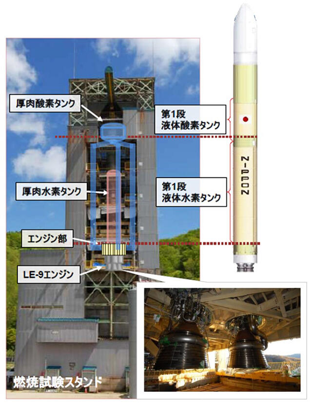
Firing test scene |
Mar. 8, 2019 Updated
The LE-5B-3 engine development test is completed!
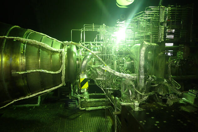
On February18, 2019, voices echo inside the Measurement and Control Building of the High Altitude Test Stand at the Kakuda Space Center in Miyagi Prefecture. "130 seconds have passed since the firing started. The combustion will soon be ceased. Five, four, three, two, one, stop combustion. The development of the upper stage engine consists of tests of two prototype engines, with one engine tested in the first test series from March to October 2017 and the other in the second test series from November 2018 to February 2019. In each series of test, firing test will be conducted for 15-20 times with a cumulative total of about 50 minutes to determine whether the engine is designed properly. Every day during the test period is critical. As a rocket engine operates under high pressure and high temperature, carelessness could lead to a major accident. If that happens, the test has to start from scratch. For this reason, the staff in charge of development scrupulously determine test conditions each time, carefully conduct the test and examine results of the test in detail. Especially towards the end of a test series, staff members will act more carefully, more cautiously and more meticulously because they don't want to waste cumulated test results. Stay focused. We will make the project successful. When that kind of tension is at its peak, there is only a sigh of relief after a test ends successfully. The upper stage engine development tests were completed and JAXA will move on to the next stage, which are the test in which the upper engine mounted on a rocket (captive firing test (CFT)) and the launch of the first prototype rocket. It's like a relay at a sports day, where you run through your turn and hand the baton off to the next person. But we will be watching and supporting the baton (the upper stage engine) all the way to the finish line. Stay focused. We will absolutely make the project successful. People in such spirit are developing H3 Launch Vehicle. 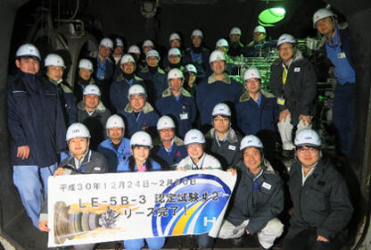
Group photo after the certification test 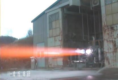
Testing at MHI's Tashiro Test Facility 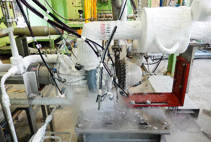
Testing of a liquid hydrogen turbo pump |
Feb. 12, 2019 Updated
The maintenance of new Dollies for H3 Launch Vehicle is under way at the Tanegashima Space Center.
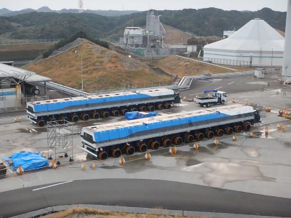
Last time, we introduced the Movable Launcher (hereinafter referred to as “ML”) for H3 Launch Vehicle. This time, a very powerful “ML transporter (commonly known as a "Dolly"), which is used to transport the ML, is introduced. 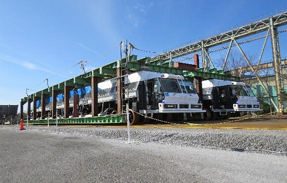
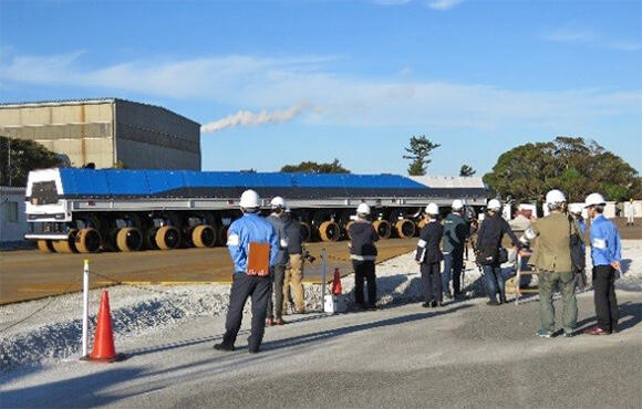
The company that built the new Dollies this time is Nippon Sharyo Ltd. For the first time, a company famous for manufacturing railroad cars including the bullet train is engaged in the development of space-related equipment. On December 5 (Wed), Nippon Sharyo Ltd., jointly with Mitsubishi Heavy Industries, Ltd., unveiled the new dollies to the media at its plant in Handa City, Aichi Prefecture. It had been raining until the day before, but on the day of the opening, the weather was almost perfect and sunny, and 36 members from 18 press companies from across the country attended the event. After opening the dollies to the press, they will be transported to Tanegashima Island where the launch site is located. Because it is a very large and heavy structure, each one is divided into three parts and some of the wheels are removed and transported by ship and special vehicle. The dollies arrived on January 14 (Mon) this year at Shimama Port of Tanegashima Island where the launch site is located. The movement of the dollies within Tanegashima Island will take place at night as in the case of rocket body. Six trucks loaded with split dollies are slowly making their way to the Tanegashima Space Center. The final assembly and maintenance work are now under way at the Tanegashima Space Center, and JAXA is planning to conduct a test by combining a Dolly with the ML. The development of equipment for supporting H3 Launch Vehicle is also making steady progress. 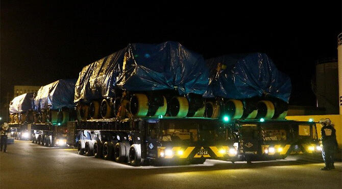
The structure on top of the dollies an imitation of the ML 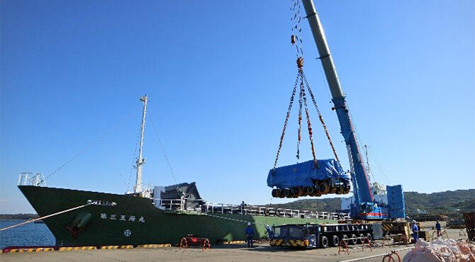
A scene of unveiling a new dolly to the press. 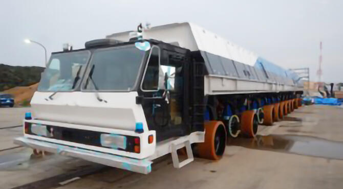
A scene of new dollies departing from the plant of Nippon Sharyo Ltd. 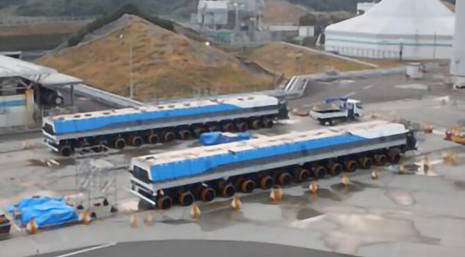
Part of dolly being unloaded from the ship at Shimama Port. The new dollies are heading for Tanegashima Island. |
Nov. 22, 2017 Updated
LE-9 Engine Assembled for Testing Shown to the Media
|
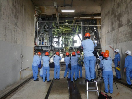
On November 14, 2017, JAXA invited to the JAXA Tanegashima Space Center (TNSC) the member of the media to see the LE-9 engine assembled for tests. The rain at the site hardly detracted many from around the country to look at the LE-9 model installed in the TNSC firing test chamber.
|
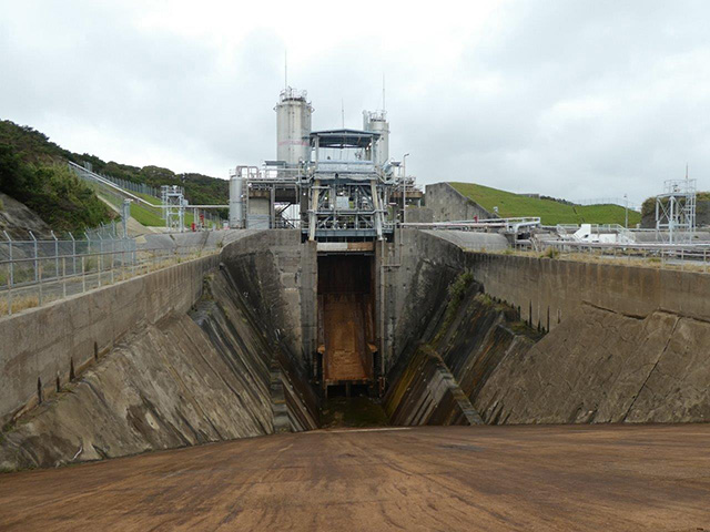
|
|---|
Oct. 12, 2017 Updated
H3 Scaled Acoustic Reduction Experiments
|
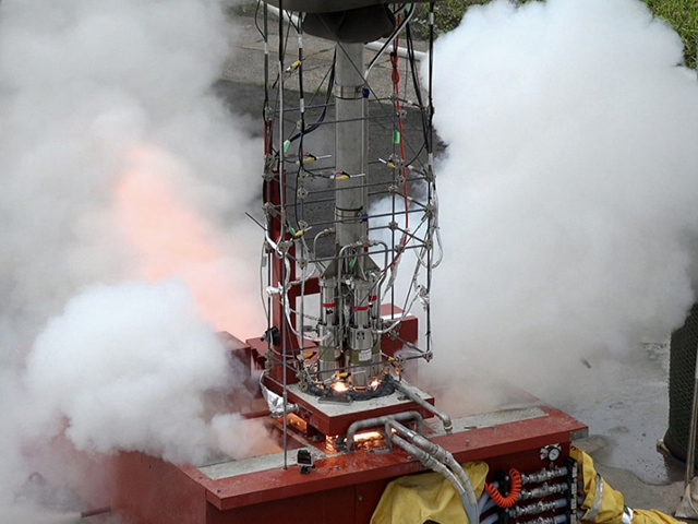
During launch, a rocket makes huge noise equivalent to hundred large passenger jet engines. The acoustic energy can cause damage to its payload as well as the rocket itself. To minimize it, H3 that JAXA is now developing seeks to achieve the world’s quietest launch. As part of the noise reduction program, HARE (H3 Scaled Acoustic Reduction Experiment) was carried out from April to July, at the JAXA Noshiro Rocket Test Center, Akita. The water system is designed to protect the Shuttle and its payloads from any damage that may occur from acoustical energy reflected from the Mobile Launcher Platform (MLP) during launch. 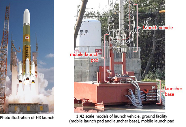
|
|
|---|
Aug. 8, 2017 Updated
LE-9 Turbopumps Unit tests
|
Unit tests of the turbopumps, components of the LE-9 engine, are underway at the JAXA Kakuda Space Center. The oxygen and fuel turbopumps are LE-9's essential parts, responsible for supplying liquid oxygen and liquid hydrogen fuel to the engine's main combustion chamber. The liquid hydrogen turbopump delivers 750 liters, or four drum containers of cryogenic liquid hydrogen per second into the LE-9's combustion chamber. The turbopumps mounted on the replicated LE-9 engine undergo a series of testing to ensure their function and performance. At the Kakuda Center, there is a burn pond for disposal of hydrogen gas boil-off. Boiling off unused liquid hydrogen to dissipate produces a towering blaze that can reach fifty meters. Images of LE-9 development is available in the video below with excerpts from the unit testing. |

|
|---|
Jun. 30, 2017 Updated
Updates on Development of LE-5B-3 Engine – Firing Test Begins
|
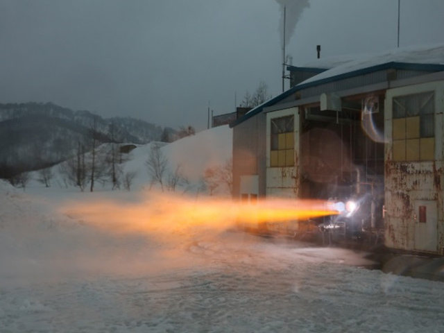
JAXA tested LE-5B-3, the liquid rocket engine designed to propel the second stage of H3 Launch Vehicle now under development. LE-5B-3 enhances the LE-5B-2 engine that likewise boosts the second stage of H-IIA and H-IIB. LE-5B-2 has earned the time-tested record of reliability after scores of successful H-II launches. Improvements are being made to lower the cost of LE-5B-3, without compensating the dynamics to blast off H3, a larger rocket and to sustain its flight. Following the design improvements for affordability and performance which reached the desired level in August 2016, JAXA successfully conducted the test of the liquid hydrogen turbopump in December 2016 through January 2017. The liquid hydrogen turbopump -- equivalent of the heart of a human body -- draws in the propellants into the engine thrust chamber. Since March 2017, the first engine with the hydrogen turbopump, assembled for certification was completed, kicking off its preliminary firing testing. The test is proceeding on schedule. By September 2017, test results will expectedly prove the soundness of the basic design improvements. |
|
|---|
Jun. 15, 2017 Updated
JAXA Gives SRB-3 Development a Boost
|
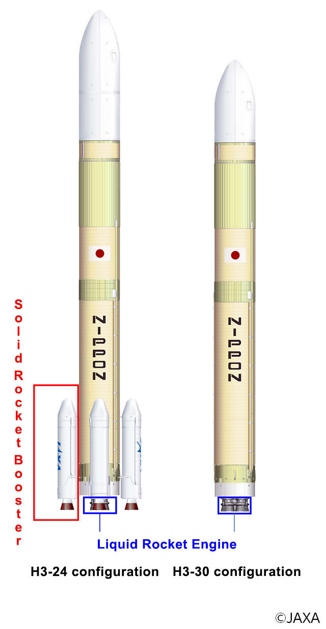
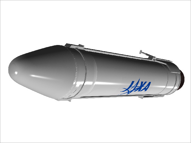
SRB-3 is an auxiliary rocket, also now under development as solid rocket booster to be attached to the base of the H3 rocket. Strap-on solid rocket boosters derived from SRB-3 reinforce H3’s launch capabilities. Varied configuration – zero, two or four booster(s), depending on the desired thrust – gives the launch vehicle a higher degree of flexibility, one of its strengths. JAXA pursuits cost reduction by use of the technology that produced SRB-A, H-II rocket’s first stage engine, and simplification of the attachment methods. The SRB-3 rocket motor, almost the same size as SRB-A’s, is also configured for the first stage of the Epsilon launch vehicle. Based on the design review, since April 2017, JAXA has started testing motor strength using the full-scale motor case. SRB-3 is subject to a series of tests, including ground firing and separation. |
|
|---|
Apr. 28, 2017 Updated
H3 Makes Debut in Computer Graphics
|
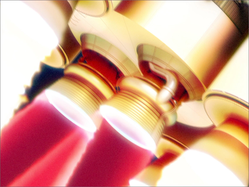
Computerized images of JAXA's H3 rocket, to be launched in Japanese fiscal 2020, have been available to the public. |
|
|---|
Mar. 31, 2017 Updated
LE-9 Engine Assembled, Shipped for Testing
|
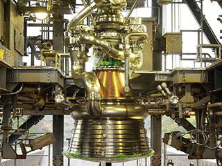
On March 31, in Tanegashima Space Center, LE-9 engine for the new H3 type of launch vehicles was installed on the facility’s firing test stand used for liquid fuel boosters. The test schedule will be available on the website as soon as determined. |
|
|---|
Jul. 7, 2016 Updated
Logo mark for development of H3 Launch Vehicle created
|
JAXA created a logo for the development of the H3 Launch Vehicle to unify engineers' minds with a single goal. |

|
|---|
