Topics List
Jan. 11, 2017 Updated
Completion of KIKU No. 8 Operation
|
At 3:25 p.m., (Japan Standard Time) January 10, 2017, JAXA terminated its Engineering Test Satellite-VIII KIKU No.8 (ETS-VIII) transmission, thus brought a closure to the satellite’s operation. |
|
|---|
Oct. 25, 2012 Updated
KIKU No.8 starts data transmission test from GPS tsunami gauge
|
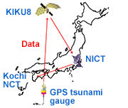
JAXA started a data transmission test from a GPS tsunami gauge through the Engineering Test Satellite-VIII KIKU No.8 (ETS-VIII) on Oct. 24 in cooperation with the National Institute of Information and Communications Technology (NICT), Hitachi Zosen Corporation, the Earthquake Research Institute of The University of Tokyo, and Kochi national College of Technology. |
|
|---|
May 16, 2011 Updated
KIKU-VIII completes support for disaster measures
|
JAXA provided a broadband environment using the Engineering Test Satellite VIII “KIKU No. 8” (ETS-VIII) in Ohfunato city and Ohtsuchi town in Iwate Prefecture as part of support activities for disaster measures after the Great East Japan Earthquake. The environment was used for information gathering and dispatching. We have also offered communication lines to Onagawa town in Miyagi Prefecture. Since the ground communication infrastructure has been recovered there, support using the KIKU No. 8 was completed according to a request from Onagawa town. |
|
|---|
Mar. 24, 2011 Updated
Satellite communications using KIKU No. 8 to support disaster measures following Tohoku Region Pacific Ocean Coastal Earthquake
|
JAXA began a satellite communication connection using the Engineering Test Satellite VIII "KIKU No. 8" (ETS-VIII) to support disaster measures following the Tohoku Region Pacific Ocean Costal Earthquake. |
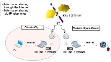 Conseptual diagram of communication system |
|---|
Jun. 2, 2010 Updated
KIKU No. 8 completed regular operation phase
|
The KIKU No. 8 launched in December 2006 completed its three-year regular operation phase, and moved to the post-operation phase. The KIKU carried out verification experiments on communication lines at disaster preparation training and communication tests with small mobile terminals. |
 |
|---|
Dec. 8, 2008 Updated
Remote control of deep-sea surveyor using the KIKU No. 8 successfully verified
|
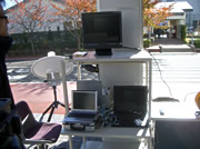
Japan Energy for Marine-Earth and Technology (JAMSTEC) developed the remote control system for a deep-sea surveyor using the Engineering Test Satellite No. 8 "KIKU No. 8," and carried out a verification test of the system. The test was successful as the small deep-sea surveyor "MROV," with its high definition TV camera (HDMROV), was remotely controlled via the KIKU No. 8 to operate deep in the sea while images under the ocean was monitored at the ground base station. |
 |
|---|
May 27, 2008 Updated
Satellite communication system experiment with "KIKU No. 8" during emergency drill in Kagoshima
|
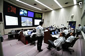
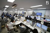
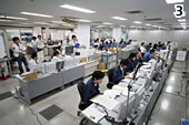
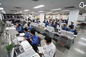
The satellite communication system using the Engineering Test Satellite VIII (ETS-VIII), or the “KIKU No. 8,” was tested during an emergency drill held by the Kagoshima Municipal Government. IC tags with individual residents' data was distributed to residents before the experiment. During the drill, information recorded in each IC tag was read at each evacuation shelter, then all the data was sent to the base command station from the shelters via the “KIKU No. 8.” From this data transmission, the base command station can grasp the status of each shelter, including how many residents are at respective shelters and their identity, in real time. Through this experiment, we were able to prove the effectiveness of the communication method covering broader areas and the convenience of using IC tags in case of an emergency by connecting physically separated emergency shelters via the “KIKU No. 8.” 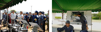 (Left: Governor Ito at the base station. Right: Confirming the status of each shelter) |
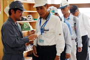 (Photo: Accepting evacuees by reading their IC tags) |
|---|
Apr. 14, 2008 Updated
Large Deployable Antenna Reflectors (LDAR) on "KIKU No. 8" (ETS-VIII) receive awards from Japan Society of Mechanical Engineers
|
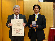
The Large Deployable Antenna Reflectors (LDAR) on the “KIKU No. 8” (ETS-VIII), which was launched in December 2006, were awarded a medal for Distinguished Engineering by the Japan Society of Mechanical Engineers. |
 |
|---|
May 10, 2007 Updated
"Kiku No. 8" shifted to regular operation
|
The "Kiku No. 8," which was injected into its scheduled Geostationary orbit (at an east longitude of 146 degrees) by six orbit controls and checked for the health of both the bus and sub systems and mission equipment, was moved from the initial phase to the regular operation phase as a result of a review for starting regular operations. |
 |
|---|
Dec. 27, 2006 Updated
KIKU No. 8 completes LDR deployment moving to the Initial Functional Verification Phase
|
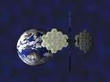
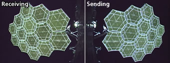
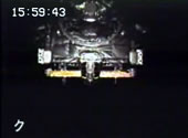
The KIKU No. 8 (ETS-VIII), which was injected into the drift orbit after four rounds of apogee engine firing, started to deploy the receiving antenna of its large deployable antenna reflector (LDR) at 5:31p.m. on Dec. 25 and the sending antenna at 6:56 p.m. on Dec. 26. Both these antennas were confirmed to be successfully deployed through telemetry data and images from onboard cameras sent from the satellite on the respective days. At 4:14 a.m. on the 27th, the attitude control mode was shifted to the regular control mode to advance to the initial functional verification phase. |
 |
|---|
Dec. 25, 2006 Updated
KIKU No. 8 is in Critical Phase
|
The KIKU No. 8 (ETS-VIII) launched on Dec. 18 from the Tanegashima Space Center is now operating in the "Critical Phase." Injected into the geostationary transfer orbit by the H-IIA Launch Vehicle, the KIKU No. 8 is increasing its orbit altitude step by step through firing of the apogee engine. After reaching the drift orbit by firing four times, the large deployable antenna reflectors will be deployed. The attitude control mode will then be shifted to the regular mode to complete its Critical Phase. |
    |
|---|
Dec. 18, 2006 Updated
KIKU No. 8 deployed solar array paddles
|
The Japan Aerospace Exploration Agency (JAXA) received signals from "KIKU No. 8" at the Santiago Station in Chile and the Maspalomas Station in the Canary Islands (the Kingdom of Spain). Through the received signals and images, we have confirmed that solar array paddles have been deployed and sun acquisition was successfully performed. |
 |
|---|
Dec. 18, 2006 Updated
KIKU No. 8/H-IIA F11 successful launch and payload injection
|
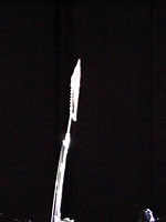
The H-IIA Launch Vehicle No. 11 (H-IIA F11) with the Engineering Test Satellite VIII "KIKU No. 8" (ETS-VIII) onboard was launched at 3:32 p.m. on December 18, 2006 (Japan Standard Time, JST.) The launch vehicle flew smoothly, and, at about 28 minutes after liftoff, the "KIKU No. 8" separation was confirmed. |
 |
|---|
Dec. 16, 2006 Updated
Launch postponement of the KIKU No. 8/H-IIA F11
|
The launch of the KIKU No. 8/H-IIA F11 scheduled on Dec. 16 has been postponed due to clouds including a freezing layer observed above the launch site. There is little possibility for the weather to recover by the time of the launch. |
|
|---|
Dec. 11, 2006 Updated
KIKU No. 8 onboard the H-IIA
|
Launch preparation operations are underway for the KIKU No. 8 at the Tanegashima Space Center. |
 |
|---|
Dec. 8, 2006 Updated
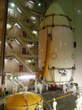
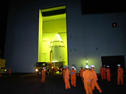
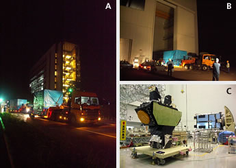
Encapsulated KIKU No. 8 moved to the VAB Countdown to launch
|
The "KIKU No. 8 (ETS-VIII)," which had been encapsulated by fairing at the Spacecraft and Fairing Assembly Building (SFA), left the SFA for the Vehicle Assembly Building (VAB) on the night of Dec. 7. The transportation went smoothly. In the VAB, the encapsulated KIKU No. 8 will be loaded onto the launch vehicle to be ready for the coming launch. |
 |
|---|
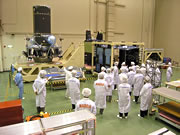
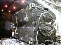
Nov. 6, 2006 Updated
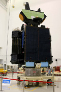
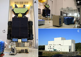
Kiku No.8 (ETS-VIII?open to the press
|
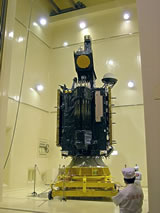
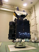
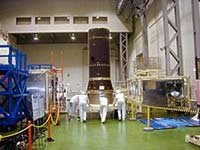
The Engineering Test Satellite "Kiku No. 8 (ETS-VIII), which arrived at the Tanegashima Space Center in September, was open to the press on Nov. 1, and the satellite showed its body wrapped in black insulation material with its stowed antennas and solar array paddles. The stowed Kiku is 7.3 meters in height, 3.7 meters in length, and 4.6 meters in width. It will be 5.8 tons (at the time of liftoff), which is the heaviest satellite in Japanese satellite history. Its launch vehicle, H-IIA F 11, is equipped with four solid rocket boosters (SRB-As), two more SRB-As than the conventional H-IIA with two SRB-As, to increase launch capability. |
 |
|---|
Oct. 30, 2006 Updated
Final preparation is underway for launch
|
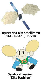
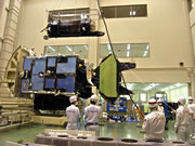
Various activities are underway ahead of the launch of the "Kiku No. 8" including announcements about the launch day, its nickname, and its symbol character "Kiku Hachi-zo." The "Kiku No. 8 (ETS-VIII)," which had been delivered to the TNSC, was unpacked and reassembled, and a final functional verification test was carried out. |
 |
|---|
Oct. 27, 2006 Updated
Launch day is set! Special site is open!
|
The launch day of the Engineering Test Satellite VIII "Kiku No. 8 (ETS-VIII)" is set for December 16, 2006. We have opened a special site to provide you with the latest information about "Kiku No. 8 (ETS-VIII)" and H-IIA Launch Vehicle No. 11 (H-IIA No.11.) Please enjoy this site. |
 |
|---|
Oct. 23, 2006 Updated
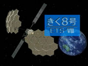
Engineering Test Satellite VIII (ETS-VIII) nicknamed "Kiku No. 8"
|
The Engineering Test Satellite VIII (ETS-VIII) was nicknamed "Kiku No.8" ("Kiku" means "chrysanthemum" in English.) The ETS series has been named "Kiku" since its first satellite. |
 |
|---|
Oct. 16, 2006 Updated
LDREX-2 antenna deployment confirmed
|
Concerning the deployment experiment of the Large Deployable Reflector Small-sized Partial Model 2 (LDREX-2) launched by the Ariane 5 launch vehicle at 5:56 a.m. on Oct. 14, 2006 (Japan Standard Time) JAXA confirmed the antenna deployment by images acquired at the Malindi Station in the Republic of Kenya. It is expected to take a week to 10 days to find the final result of the deployment experiment as we have to analyze telemetry data acquired during the experiment. |
 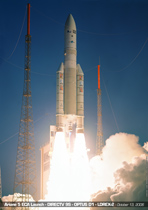 [c2006 ESA-CNES-ARUANSPACE / Photo Optique Video CSG]
|
|---|
Oct. 13, 2006 Updated
ETS-VIII arrived at the TNSC
|
The Engineering Test Satellite VIII (ETS-VIII), which completed the System Proto-flight Test (System PFT) at the Tsukuba Space Center (TKSC), was delivered to Tanegashima from Tsukuba. |
 |
|---|
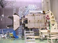
Aug. 21, 2006 Updated
Final electric performance test underway at TKSC
|
The ETS-VIII is currently undergoing its final electric performance test, which is the last part of the series of tests for the System Proto Flight Test (System PFT) at the Tsukuba Space Center (TKSC.) |
  |
|---|
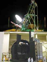
Apr. 10, 2006 Updated
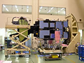
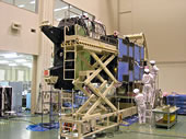
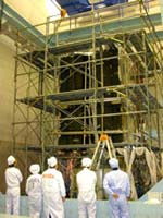
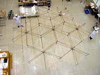
ETS-VIII: Deployment test of the reflector surface of the LDR
|
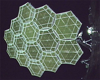
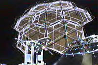
JAXA carried out a deployment test for the reflector surface of the Large-scale deployable antenna reflectors (LDR) of the Engineering Test Satellite (ETS-VIII) on April 7 in Tokyo. The ETS-VIII is scheduled to be launched in Japanese Fiscal Year 2006. The LDR is the largest deployable antenna in the world. |
  |
|---|
Jan. 27, 2006 Updated
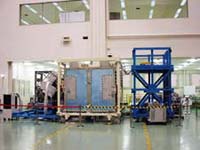
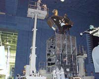
Mechanical environmental test performed on the satellite
|
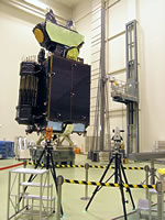
The ETS-VIII is undergoing a system proto-flight test (System PFT) to ready it for the launch. After the mass property test was carried out, a "mechanical environmental test" was held on the ETS-VIII, whose assembly had been completed. In this test, to make sure no problems arise, the satellite is under a simulated mechanical environment, such as vibrations, acoustic environment, and shocks, which the satellite will experience at the time of launch.
|
|
|---|
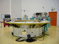
Oct. 28, 2005 Updated
Restarting the system proto-flight test
|
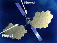
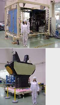
The ETS-VIII team has resumed its system proto-flight test (PFT) of the satellite, after its assembly was completed. The PFT being held at the Spacecraft Integration and Test Building (SITE) at the Tsukuba Space Center is a series of tests to verify if the assembled satellite functions properly. The ETS-VIII, which had already completed an electric performance test, just finished the alignment test to precisely measure the position and direction of satellite sensors and thrusters using the principle of the triangular surveying (Photo 1), and a mass property test for measuring the mass, center of the gravity, and inertial moment (Photo 2: measuring the center of the gravity). These test results are basic data for satellite attitude control and interface with the launch vehicle. We are scheduled to conduct vibration, acoustic, and shock tests from now to check the mechanical environment. |
|
|---|
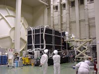
Aug. 3, 2005 Updated
Assembly is completed, and the test will be resumed soon.
|
After the ETS-VIII system checkup, the ETS-VIII team has been preparing to resume the system proto-flight test (System PFT). By the end of July, we completed satellite assembly operations by installing the external equipment including the "Large Deployable Reflector (LDR)", the "Solar Array Paddles (PDL)", and the "Deployable Radiator". We are now ready for the System PFT. |
  |
|---|
Apr. 27, 2005 Updated
LDREX-2 deployment experiment on an aircraft successful
|
On April 5, 2005, the ETS-VIII project team carried out a deployment test on the Large Deployment Reflector smaller and partial model #2 (LDREX-2) in a quasi zero-gravity (or microgravity) environment by loading it on an airplane. A microgravity environment can be created by an airplane ascending steeply, turning the engine almost off, then descending sharply. The environment can be maintained only for 20 seconds at one time. All objects will weigh twice as much for 20 seconds before and after the effects of microgravity. The aircraft ascends and descends to a height of 2,400 meters in a minute. For our test, the airplane created a microgravity environment 13 times during its three-hour flight. |
 |
|---|
Mar. 31, 2005 Updated
In-orbit deployment test for the LDR using its small and partial model
|
As a result of the ETS-VIII System Checkup, the ETS-VIII team decided to carry out an in-orbit deployment test for the Large Deployment Reflector (LDR) using its smaller and partial model #2 (LDREX-2). |
 |
|---|
Mar. 10, 2005 Updated
System checkup completed and ETS-VIII development resumed
|
The ETS-VIII team has been carrying out a system checkup since March 2004 by suspending the system plot flight test because it has been determined that satellite projects in the development phase need a system checkup in response to successive anomalies found in the Mars probe "Nozomi" and the Earth observation satellite "Midori-II". |
 |
|---|
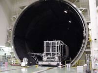
Jan. 15, 2004 Updated
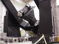
Thermal vacuum test for the satellite system was completed.
|
A thermal vacuum test was carried out for ETS-VIII in a 13-meter diameter space chamber in the Spacecraft Integration and Test Building (SITE) at the Tsukuba Space Center. The test is part of the system proto-flight test (system PFT). |
  |
|---|
Oct. 14, 2003 Updated
The initial electric performance test of the flight model was conducted.
|
The ETS-VIII, whose main body was assembled, is under the System Protoflight Test (PFT). After the initial visual inspection following the assembly, initial electric performance test data were acquired by connecting the satellite and test equipment by cables. The purpose of this data acquisition is to verify the electric performance of the overall satellite, and we confirmed that the ETS-VIII operated as designed. |
 |
|---|
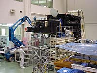
Sep. 10, 2003 Updated
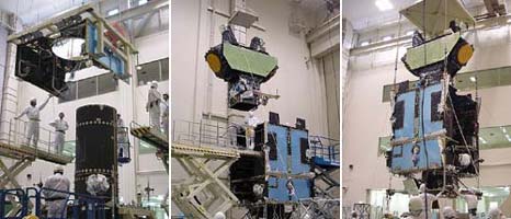
The satellite main body was assembled.
|
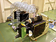
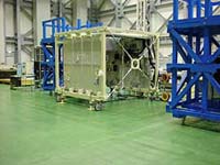
First, the "propulsion module" and the "bus module" were connected (Photo : Left), then the "payload module" was placed on them to construct a box-shaped satellite body. |
 |
|---|
Jul. 29, 2003 Updated
The flight models of the large deployable antennas are now being tested.
|
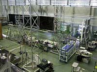
The large deployable antennas (LDRs), which will be as large as a tennis court when they are deployed in orbit, are characteristic modules of the ETS-VIII. |
 |
|---|
Apr. 14, 2003 Updated
Modules for ETS-VIII are being delivered to the Spacecraft Integration and Test Building (SITE)
|
The satellite system of ETS-VIII is currently being assembled for a comprehensive test staring in Japan Fiscal Year (JFY) 2003. For ETS-VIII, each module is manufactured and tested respectively first to verify conditions of each, then the modules are assembled as a satellite system. The assembly is scheduled to be conducted at the Tsukuba Space Center (TKSC), thus those which are ready to be assembled are being delivered to the Spacecraft Integration and Test Building (SITE). |
 |
|---|
Feb. 4, 2003 Updated
Tests on the payloads of the Flight Model have been performed continuously at Tsukuba Space Center as part of the ETS-VIII project.
|
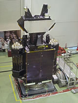
The airframe of ETS-VIII is structured with modules from its top to the bottom, including an antenna tower, payloads, bus systems and propulsion systems. Thus the production and tests for each module can be simultaneously performed effectively. |
 |
|---|
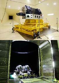
Nov. 22, 2002 Updated
|
The thermal design and analysis validity of Flight Model payloads were evaluated in the vacuum chamber simulating the space environment (for vacuum, low temperature and sun light) and confirmed that the quality is suitable for the actual flight. The top-left photo shows the thermal vacuum test for the Feeder Link Antenna (FL-ANT) and the lower-left photo shows the thermal balance test for the TX Large-scale Deployable Reflector (TX LDR.). |
 |
|---|
Apr. 20, 2001 Updated
ETS-VIII SSM Development Tests
|
ETS-VIII Satellite System Structure Model(SSM) has been subject to structure tests, to verify the structure design against launch environments such as shock, acoustic, sinusoidal, and random vibrations, at Tsukuba Space Center/Satellite Integration Test Facility from late March through mid June. |
 |
|---|
Mar. 27, 2001 Updated
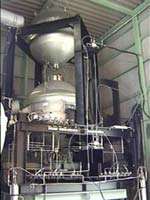
System Thermal Model (STM) for Thermal Vacuum Test
|
STM is an engineering model of ETS-VIII Satellite System to check out the validity of thermal design for on-orbit vacuum environment. STM has been subject to Thermal Vacuum Chamber Test at MELCO/Kamakura Works from late February through March. |
 |
|---|
Dec. 8, 2000 Updated
LDREX Launch and Deployment Experiment
|
Large-scale Deployable Reflector Experiment Model(LDREX), about six meters in diameter, is a half-scale model of seven modules for the ETS-VIII LDR to validate its essential design of deployment mechanism prior to the full flight-model fabrication. The LDREX is to be launched as a piggyback by Arian-5 Rocket on Dec. 21, for its almost 20-minute deployment demonstration on orbit. |
 |
|---|
Dec. 6, 2000 Updated
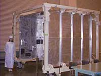
ETS-VIII Satellite System Structure Model (SSM) Static Load Tests
|
ETS-VIII Satellite Body is two-story-box, with each Panel installed with various equipment inside, and has Central Cylinder, an load-supporting inner structure, accommodates two propellant tanks (upper and lower) in itself, and attaches Apogee Engine to its lower end cone. |
 |
|---|
Aug. 18, 2000 Updated
LDR Radio frequency Tests
|
Large Deployable Reflector (LDR) has been under RF (radio frequency) measurement tests from late July to mid August to verify its antenna radiation patterns by combining the LDR Model (seven module type) with the Phased Array Feeders at Radio wave Test Facility in Toshiba/Komukai Works. |
 |
|---|
Jul. 14, 2000 Updated
SEM under System Tests
|
System Engineering Model (SEM) is an electrical function model of ETS-8 Satellite to verify overall electrical performance with system tests if the design is ready for Flight Model fabrication. SEM consists of Bus Module(upper stage), Payload Module(middle), and Propulsion Module(lower), integrated into satellite structure with wire harness. |
 |
|---|
May 19, 2000 Updated
Large Deployable Antenna EM Thermal Vacuum Test
|
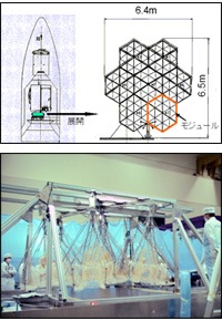
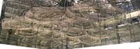
Large Deployable Antenna will be packed in a 1 m (diameter) × 4 m (length) cylindrical shape upon launch and deployed on orbit to make a tennis-court-size parabola by expanding her 14 umbrella-like modules simultaneously while jointing their rib-edges to the others. |
 |
|---|
Mar. 10, 2000 Updated
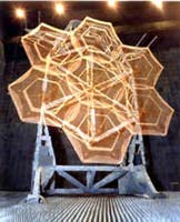
Large Deployable Antenna EM Deployment Test
|
Large Deployable Antenna, packed in a cylindrical shape upon launch, will be deployed on orbit to make a tennis-court-size parabola by expanding her 14 umbrella-like modules simultaneously while jointing their rib-edges to the others. |
 |
|---|
Feb. 14, 2000 Updated
ETS-VIII Central Cylinder Static Load Tests
|
ETS-VIII Satellite has Central Cylinder, an inner structure, that balances out all loads, accommodates two propellant tanks (upper and lower) inside, and attaches Apogee Engine to its lower end cone. |
 |
|---|
Jan. 31, 2000 Updated
ETS-VIII Antenna Tower under Thermal Balance Test
|
Antenna Tower is equipped with FL Antenna, HAC Antenna, Phased-Array Feeder(transmitting and receiving feeders for respective LDR antennas, and two heat-radiation-panels), and Sensor Mast. This thermal model of Antenna Tower has been subjected to the thermal balance tests conducted at Tsukuba Space Center in late December, and is verifying its thermal control design to maintain the temperature within a specific range under space environment. |
 |
|---|
Dec. 10, 1999 Updated
Solar Paddle Deployment Test
|
The deployment test of ETS-VIII Solar Paddle(EM) has been conducted at TOSHIBA/Komukai Works in November to December. The Paddle folds in four 2.5m x 3.3m honeycomb-panels and expands out on orbit. Upon its ground test, the Paddle is suspended by cables to cancel gravity so that we can simulate and verify the on-orbit deployment operation. |
 |
|---|
Nov. 12, 1999 Updated
ETS-VIII/SEM Integration Started
|
System Engineering Model (SEM), the satellite structure installed with Engineering Models of bus and mission equipment, verifies overall electrical performance whose test data will be of use to Flight Model's design. First of all, assembly and wiring of Payload Module (upper section of satellite structure) for mission equipment has been started at Melco/Kamakura Works in October, and then its functional test will be done until January 2000. |
 |
|---|
Oct. 15, 1999 Updated
LDR-P Antenna Deployment Test
|
Large Deployable Antenna Reflector (LDR) of ETS-VIII will be launched as folded and deploy its 14 umbrella-like modules side by side on a geostationary orbit to form an antenna reflector in an elliptic shape (approximately 17m×19m in outside diameter) . |
 |
|---|
Sep. 10, 1999 Updated
Propulsive SFT for ETS-VIII is underway.
|
System Firing Test (SFT) for perfect bipropellant chemical propulsive system (fuel: MMH, oxidizer: MON-3) of ETS-VIII has been conducted at Aioi Factory since the middle August and will be ended in the end of September. By conducting the verification test by actually firing 500N class apogee engine (AKE) which to be used in launching geosynchronous orbit, and 20N class biproopellant thruster which to be used in attitude and orbit control through the ground test model, this SFT will confirm the operational characteristics which are necessary in the orbit and its procedure in the management. The objective of SFT is to reflect the result on the production of propulsive flight model. |
 |
|---|
Jul. 26, 1999 Updated
|
Integration of Engineering Model(EM) for ETS-VIII mission equipment started on June 14-th Mobile communication experiment equipment (EM-class) is being integrated into mission panels of the ETS-VIII payload module (upper section of satellite structure) at Spacecraft Integration and Test Facility(SITE), Tsukuba Space Center. This mission equipment has been developed by ETS-8 cooperative organizations such as ASC, CRL, and NTT (Most of their EM will be refurbished and upgraded for flight ). After assembled, the mission panels will be checked out on communication systems, and handed over to NASDA by the end of August. |
 |
|---|